Dossier Océan et énergie - Énergie Thermique des Mers
Sommaire IOA News Letters
Ocean Thermal Energy Conversio(OTEC)I
by
L. A. Vega. Ph. D.,
Hawaii, USA
Summary
The vertical temperature distribution in the open ocean can be simplistically described as consisting of two layers separated by an interface. The upper layer is warmed by the sun and mixed to depths of about 100 m by wave motion. The bottom layer consists of colder water formed at high latitudes. The interface or thermocline is sometimes marked by an abrupt change in temperature but more often the change is gradual. The temperature difference between the upper (warm) and bottom (cold) layers ranges from 10 ¢XC to 25 ¢XC, with the higher values found in equatorial waters. To an engineer this implies that there are two enormous reservoirs providing the heat source and the heat sink required for a heat engine. A practical application is found in a system (heat engine) designed to transform the thermal energy into electricity. This is referred to as OTEC for Ocean Thermal Energy Conversion.
Several techniques have been proposed to use this ocean thermal resource; however, at present it appears that only the closed cycle (CC-OTEC) and the open cycle (OC-OTEC) schemes have a solid foundation of theoretical as well as experimental work. In the CC-OTEC system, warm surface seawater and cold seawater are used to vaporize and condense a working fluid, such as anhydrous ammonia, which drives a turbine-generator in a closed loop producing electricity. In the OC-OTEC system seawater is flash-evaporated in a vacuum chamber. The resulting low-pressure steam is used to drive a turbine-generator. Cold seawater is used to condense the steam after it has passed through the turbine. The open-cycle can, therefore, be configured to produce desalinated water as well as electricity.
Records available from experimental plants demonstrate technical viability and provide invaluable data on the operation of OTEC plants. The economic evaluation of OTEC plants indicates that their commercial future lies in floating plants of approximately 100 MW capacity for industrialized nations and smaller plants for small-island-developing-states (SIDS). Unfortunately, the size of the experimental plants (< 0.3 MW) is about two orders of magnitude less than the size required for commercial (i.e., cost competitive) systems in industrial nations. Data extrapolation of this order is not acceptable to banking institutions or developers. The records that are available, however, are sufficient to design an OTEC plant sized at approximately 1.5 to 2 MW. This size range is appropriate for the smaller markets encountered in SIDS.
To proceed beyond experimental plants and towards commercialization in developed nations, a scaled version of a 100 MW plant must be designed and operated. The operational data is needed to earn the support required from the financial community and developers. Considering a 4-module system, a 1/5-scaled version of a 25 MW module is proposed as an appropriate size. The 5 MW pre-commercial plant is also directly applicable in some SIDS.
Short contents list
1)Background
2) Technical Limitations
3) OTEC and the Environment
4) Engineering Challenges
5) Open Cycle OTEC
6) The 210 kW OC-OTEC Experimental Apparatus
7) Design of a Small Land-Based OC-OTEC Plant
8) Closed Cycle OTEC
9) Design of a Pre-Commercial Floating Hybrid-OTEC Plant
10) Potential Sites
11) Economic Considerations and Market Potential
12) Hydrogen Production
13) Externalities
1) Background
It is estimated that, in an annual basis, the amount solar energy absorbed by the oceans is equivalent to at least 4000 times the amount presently consumed by humans. For an OTEC efficiency of 3 percent, in converting ocean thermal energy to electricity, we would need less than 1 percent of this renewable energy to satisfy all of our desires for energy. However, even assuming that the removal of such relatively small amount of ocean solar energy does not pose an adverse environmental impact we must first identify and develop the means to transform it to a useful form and to transport it to the user.
The first documented reference to the use of ocean temperature differences to produce electricity is found in Jules Verne¡¦s "Twenty Thousand Leagues Under the Sea" published in 1870. Eleven years after Jules Verne, D'Arsonval proposed to use the relatively warm (24 ¢XC to 30 ¢XC) surface water of the tropical oceans to vaporize pressurized ammonia through a heat exchanger (i.e., evaporator) and use the resulting vapor to drive a turbine-generator. The cold ocean water transported (upwelled) to the surface from 800 m to 1000 m depths, with temperatures ranging from 8 ¢XC to 4 ¢XC, would condense the ammonia vapor through another heat exchanger (i.e., condenser). His concept is grounded in the thermodynamic Rankine cycle used to study steam (vapor) power plants. Because the ammonia circulates in a closed loop, this concept has been named closed-cycle OTEC (CC-OTEC). D'Arsonval¡¦s concept was demonstrated in 1979, when a small plant mounted on a barge off Hawaii (Mini-OTEC) produced 50 kW of gross power, with a net output of 18 kW. Subsequently, a 100 kW gross power, land-based plant was operated in the island nation of Nauru by a consortium of Japanese companies. These plants were operated for a few months to demonstrate the concept. They were too small to be scaled to commercial size systems.
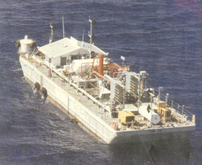

Mini-OTEC (1979)
Postage Stamp Issued by Nauru to Commemorate - CC-OTEC Demonstration Plant (1982)
Forty years after D'Arsonval another French inventor, Georges Claude, proposed to use the ocean water as the working fluid. In Claude's cycle the surface water is flash-evaporated in a vacuum chamber. The resulting low-pressure steam is used to drive a turbine-generator and the relatively colder deep seawater is used to condense the steam after it has passed through the turbine. This cycle can, therefore, be configured to produce desalinated water as well as electricity. Claude's cycle is also referred to as open-cycle OTEC (OC-OTEC) because the working fluid flows once through the system. He demonstrated this cycle in 1930 in Cuba with a small land-based plant making use of a direct contact condenser (DCC). Therefore, desalinated water was not a by-product. The plant failed to achieve net power production because of a poor site selection (e.g., thermal resource) and a mismatch of the power and seawater systems. However, the plant did operate for several weeks. This was followed by the design of a 2.2 MW floating plant for the production of up to 2000 tons of ice (this was prior to the wide availability of household refrigerators) for the city of Rio de Janeiro. Claude housed his power plant in a ship (i.e., plantship), about 100 km offshore. Unfortunately, he failed in his numerous attempts to install the vertical long pipe required to transport the deep ocean water to the ship (the cold water pipe, CWP) and had to abandon his enterprise in 1935. His failure can be attributed to the absence of the offshore industry, and ocean engineering expertise presently available. His biggest technological challenge was the at-sea installation of a CWP. This situation is markedly different now that there is a proven record in the installation of several pipes during experimental operations.
The next step towards answering questions related to operation of OTEC plants was the installation of a small OC-OTEC land-based experimental facility in Hawaii. This plant was designed and operated by a team led by the author. The turbine-generator was designed for an output is 210 kW for 26 ¢XC warm surface water and a deep water temperature 6 ¢XC. A small fraction (10 percent) of the steam produced was diverted to a surface condenser for the production of desalinated water. The experimental plant was successfully operated for six years. The highest production rates achieved were 255 kWe (gross) with a corresponding net power of 103 kW and 0.4 l s-1 of desalinated water. These are world records for OTEC.
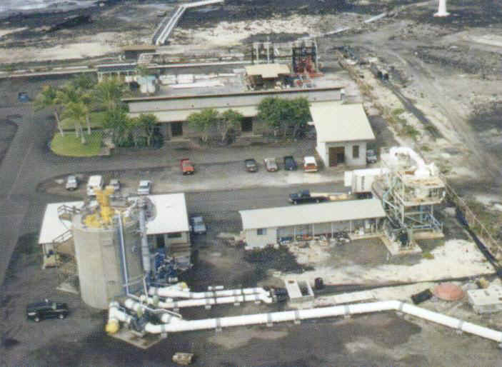
210kW OC-OTEC Experimental Plant (1993-1998)
A two-stage OTEC hybrid cycle, wherein electricity is produced in a first-stage (closed cycle) followed by water production in a second-stage, has been proposed by the author and his coworkers to maximize the use of the thermal resource available to produce water and electricity. In the second-stage, the temperature difference available in the seawater effluents from an OTEC plant (e.g., 12 ¢XC) is used to produce desalinated water through a system consisting of a flash evaporator and a surface condenser (basically, an open cycle without a turbine-generator). In the case of an open cycle plant, the addition of a second-stage results in doubling water production.
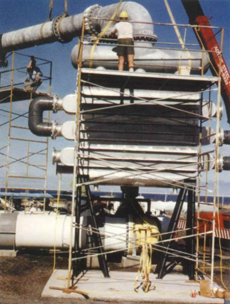
Surface Condenser for Desalinated Water Production (1994-1998)
The use of the cold deep water as the chiller fluid in air conditioning (AC) systems has also been proposed. It has been determined that these systems would have tremendous economic potential as well as providing significant energy conservation independent of OTEC. For example, to produce 5800 tons (roughly equivalent to 5800 rooms) of air conditioning only 1 m3 s-1 of 7 ¢XC deep ocean water is required. The pumping power required is 360 kW as compared to 5000 kW for a conventional AC system. The investment payback period is estimated at 3 to 4 years.
A number of possible configurations for OTEC plants have been proposed. These configurations range from floating plants to land-based plants, including shelf-mounted towers and other offshore structures. The primary candidate for commercial size plants appears to be the floating plant, positioned close to land, transmitting power to shore via a submarine power cable.
2) Technical Limitations
The performance of OTEC power generating cycles is assessed with the same elementary concepts of thermodynamics used for conventional steam power plants. The major difference arises from the large quantities of warm and cold seawater required for heat transfer processes, resulting in the consumption of 20 to 30 percent of the power generated by the turbine-generator in the operation of pumps. The power required to pump seawater is determined accounting for the pipe-fluid frictional losses and in the case of the cold seawater for the density head, i.e., gravitational energy due to the differences in density between the heavier (colder) water inside the pipe and the surrounding water column. The seawater temperature rise, due to frictional losses, is negligible for the designs presented herein.
The ideal energy conversion for 26 ¢XC and 4 ¢XC warm and cold seawaters is 8 percent. An actual OTEC plant will transfer heat irreversibly and produce entropy at various points in the cycle yielding an energy conversion of 3 to 4 percent. These values are small compared to efficiencies obtained for conventional power plants; however, OTEC uses a resource that is constantly renewed by the sun. Considering practical sizes for the cold water pipe OTEC is presently limited to sizes of no more than about 100 MW. In the case of the open-cycle, due to the low-pressure steam, the turbine is presently limited to sizes of no more than 2.5 MW. The thermal performance of CC-OTEC and OC-OTEC is comparable. Floating vessels approaching the dimensions of supertankers, housing factories operated with OTEC-generated electricity, or transmitting the electricity to shore via submarine power cables have been conceptualized. Large diameter pipes suspended from these plantships extending to depths of 1000 m are required to transport the deep ocean water to the heat exchangers onboard. The design and operation of these cold water pipes are major issues that have been resolved by researchers and engineers in the USA.
It has been determined that approximately 4 m3 s-1 of warm seawater and 2 m3 s-1 of cold seawater (ratio of 2:1), with a nominal temperature difference of 20 ¢XC, are required per MW of exportable or net electricity (net = gross - inhouse usage). To keep the water pumping losses at about 20 to 30 percent of the gross power, an average speed of less than 2 m s-1 is considered for the seawater flowing through the pipes transporting the seawater resource to the OTEC power block. Therefore, a 100 MW plant would use 400 m3 s-1 of 26 ¢XC water flowing through an 16 m inside diameter pipe extending to a depth of 20 m; and 200 m3 s-1 of 4 ¢XC water flowing through an 11 m diameter pipe extending to depths of 1000 m. Using similar arguments, a 20 m diameter pipe is required for the mixed water return. To minimize the environmental impact due to the return of the processed water to the ocean (mostly changes in temperature), a discharge depth of 60 m is sufficient for most sites considered feasible, resulting in a pipe extending to depths of 60 m.
The amount of total world power that could be provided by OTEC must be balanced with the impact to the marine environment that might be caused by the relatively massive amounts of seawater required to operate OTEC plants. The discharge water from a 100 MW plant would be equivalent to the nominal flow of the Colorado River into the Pacific Ocean (1/10 the Danube, or 1/30 the Mississippi, or 1/5 the Nile into the Atlantic). The discharge flow from 60 000 MW (0.6 percent of present world consumption) of OTEC plants would be equivalent to the combined discharge from all rivers flowing into the Atlantic and Pacific Oceans (361 000 m3 s-1). Although river runoff composition is considerably different from the OTEC discharge, providing a significant amount of power to the world with OTEC might have an impact on the environment below the oceanic mixed layer and, therefore, could have long-term significance in the marine environment. However, numerous countries throughout the world could use OTEC as a component of their energy equation with relatively minimal environmental impact. Tropical and subtropical island sites could be made independent of conventional fuels for the production of electricity and desalinated water by using plants of appropriate size. The larger question of OTEC as a significant provider of power for the world can not be assessed, beyond the experimental plant stage, until some operational and environmental impact data is made available through the construction and operation of the pre-commercial plant mentioned above.
~to be continued