Dossier Océan et énergie - Énergie Thermique des Mers
Sommaire IOA News Letters
THE PIONEER OTEC OPERATION: "LA TUNISIE"
Following is aspecial report made available by Mr. Michel Gauthier to describe the main characteristics of the OTEC vessel "La Tunisie"-a floating OTEC plant George Claude attempted to build in 1935.
George Claude was eleven years old, in 1881, when the physicist D'Arsonva1 put forward the theory that it had to be possible to produce energy by making use of the temperature difference between the deep and surface layers of tropical oceans.
Nearly forty years later, having become rich and famous (the Air Liquide Company, founded in 1906, bought and put into application his work on the liquefaction and separation of gases), George Claude will turn again to the concepts of the man he considers as his mentor.
Together with Paul Boucherot, former classmate at the Paris Physics and Chemistry Institute, he conceives of using the steam generated by the boiling of warm sea-water from the surface of tropical oceans in a vacuum chamber to power a turbo-alter-nator. This will be called the Claude/Boucherot/Process(1), and its critics will claim that the pumping of the water, and the upkeep of the vacuum will absorb more energy than the system will produce.
To demonstrate the validity of his process, G. Claude will set up a first experiment in 1926, at Ougree, using the warm cooling water from a steel blast furnace and the cold water from the river Meuse: with the slight temperature difference of 20¢J, equivalent to that found in the oceans, the apparatus works! Then, in 1931, in Cuba , he is able to prove that in actual ocean conditions, the net energetic result of a thermal ocean plant is positive.
G. Claude is then faced with the task of demonstrating that this resource can be exploited on an industrial scale.
Note: (1) French Patent#628020,registered June 21, 1927.
A Commercial Scale OTEC Plant.....
As early as 1932, following his Cuban experiment, and the demonstration, on the scale of a few dozen kilowatts, of the validity of his technical concepts, George Claude hopes to graduate to a commercial scale plant of larger power output than his Matenza Bay prototype.
Since the beginning of his work on ocean thermal energy, he is aiming at the production and distribution of electricity to consumer power grids. This implies the guarantee of uninterrupted and reliable operation of the plants, and if he could imagine that future "stations" (2) anchored in deep ocean would guarantee the "perfect" and quasi-endless stability" required, he was also aware of the fact that the cost of a true "floating island" would be out of proportion with his more immediate objective of creating the first demonstration of commercial plant of a few thousand kilowatts. He considered that a 1andbuilt facility, located sufficiently near the deep cold water supply so as to reduce the length and cost of piping, would be the only way to achieve an operation able to function at a given and guaranteed ground level power.
Note: (2): The terms in quotation marks are the ones used by G. Claude himself in the reference works used for the preparation of this article. We have kept them for their picturesque-ness , and their often remarkable actuality after a span of 50 years.
In spite of his efforts, the effects of the great depression of the 30's-"these extraordinary circumstances weighing upon the world"-do not permit him to put together the partnerships and the capital required for such an undertaking. He must then proceed alone, and rely purely on his personal fortune. Unable to reconcile his own investing capabilities and the requirements of a land-based electric power plant able to function at guaranteed ground level power, he conceives of a less costly project based on "a very different method of implementation " from the ones he had considered until then,and whose basic principle follows from the very consequences of the depression. He will acquire, at small expense, one of the many vessels that the economic stagnation has driven out of business. There, he will install an OTEC plant, but instead of selling the power produced, he will use it on board to manufacture a commodity whose commercial production will be compatible with the temporary interruptions caused by bad weather conditions. Since the city of Rio de Janeiro offers, during the southern summer, a market for industrial water-ice, and since its port is within a few hundred kilometers of a favorable OTEC zone, he decides to attempt the adventure: the first OTEC plant will be an ice factory!
In 1933, he purchases the ship "La Tunisie", and asks the Chanters de France in Dunkirk to proceed with the necessary modifications. The hot season in Brazil begins in December and ends in March. Therefore he needs to be ready to level France by August, if he wants to be on site and operational at the appropriate time.
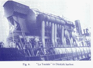
In September 1933, the M. V. La Tunisie, about 10000 tons gross and 6500 tons burrthen, iis Dunkirk . The management of the shipyard, and more particularly its director M. LeFol who is sold on G. Claude's ideas, promises every technical guarantee for the transformation work, expected to take nearly a year and employ about 500 workers and technicians (Fig 6).
1. The Power Plant
As in the Cuban experiment, the plant is designed on the "open cycle" principle. It is the boiling of sea-water in a vacuum which will supply the energy.
The ship having been freed of much of its superstructures and of its hatch covers, the 2.2MW plant consists of a cylindrical steel enclosure, vacuum resistant, with a wall thickness of 12 to 14mm. It is 23m long and 6m in diameter.
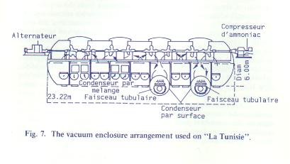
Located 10m above the waterline and in the axis of the ship, the enclosure is divided into 5 evaporator and 4 condenser compartments separated by vertical bulkheads. Each evaporator compartment, according to its position, will supply one or two turbines located on an interior plarform in the upper part of the main enclosure. The steam will then be led to condensate in the nearby condenser compartments. For reasons which will be explained later, the design provides for the separation of the steam into two equal parts, directed, one toward mixing condensers, the other toward surface condensers. The general flow is shown on Fig. 7. Each of the 2.5 meter diameter turbines is to provide 275 KW (mechanical) for a 22 ¢J temperature difference between warm and cold water (230 KW if this difference is only 20¢J).
The 8 turbines, manufactured by the Maliect et Blin Co following G. Claude's design's are fixed to a horizontal shaft running the whole length of the vacuum enclosure. To both ends of this shaft, and outside the vacuum enclosure, are coupled an 800 KW alternator (at the aft end), and a 1300KW rotary ammonia compressor for the ice-making plant (at the forward end). An auxiliary 2500KW turbo-alternator, running off the ship's boilers, provides the power required to start the plant.
The Cuban experiment allowed G. Claude to check several important aspects of the removal of gasses from sea water on a vacuum.
First, he noticed that the warm water didn't foam abundantly (which could have interfered with the running of the turbines), and that the cold water remained clear. He was then able to verify that, under OTEC conditions of temperature and pressure, 3/4 of the dissolved gasses were extracted, i.e. 15 cm3/liter out of the 20cm3/liter in solution in the surface and deep waters (the latter containing no excess of dissolved gasses on account of its pressure).Furthermore, he observed that the gas extraction method and equipment designed with the help of the engineer M. Rateau didn't consume more than 7 or 8 percent of the energy generated, instead of the 400¢Mclaimed by his detractors.
The extraction of the non-condensables takes places at 3 pressure levels. 60¢Mand 25¢Mrespectively are extracted at the 90 and 50 mbar levels. The remaining 15¢M <(which are mixed with 4 times their vloume in steam)are extracted at the 19 mbar stage of the extractor .The extractor is a 200KW Ratrau rotary compressor (mechanical, spinning at 17000 RPM,17 rotors working in series, in 5 groups separated by "surface action" cooling elements).
The intake and outflow of warm and cold water to the main enclosure are achieved by way of "barometric column", which accounts for the 10m elevation of the evaporator and condensor elements.
The water flow-7m3/sec for warm water, and 5m3/sec for cold water-is maintained by 16 propeller turbo-pumps. The warm water intake is taken, at surface level, through a 2m diameter pipe protruding out of the side of the ship. Eight pumps distribute this water to the evaporation devices. The return flow is through a 2.80 m manifold, also protruding from the side of the ship. This arrangement would prove to be excessively vulnerable to unfavorable sea-conditions, such as heavy swell, and would place the operation under "constant risk of catastrophic loss of priming". G. Claude notes, with the benefit of hindsight, that it would have been better to locate them under the belly of the ship, as was done for the cold water intake.
2. The Cold Water Intake Pipe (CWP)
The cold water intake pipe is made up of cylindrical elements, 2.5m in diameter and 1.5m long, of welded sheet steel. These elements are flanged at the ends, and are connected with bolts (100 bolts per flange.
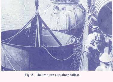
The thickness of the steel walls varies from 3.5mm for the elements near the surface to 3mm for the deeper ones. The pipe, ballasted at the bottom and kept vertical with a submerged float at the top (15m below the surface), will act as anchoring system for the factory ship. The mooring for the CWP is a cylindrical metallic container (Fig. 8) of 7m diameter, weighting 15 tons when empty. It is open on the top, and can be ballasted by filling it with iron ore. The junction between the upper portion of the CWP system, at the level of the float, and the central intake well of the ship is made by a flexible canvas pipe capable of withstanding the relative motions of both ship and float through an accordition-fold configuration, while capable as well of resisting the negative pressure created by the suction of the pumps. The whole of the metal part of the pipe on encased in a wooden insulating covering....
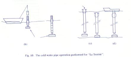
The general arrangement of the CWP, assembled on location, is shown on Fig.9.
The order of commissioniong is as follows:
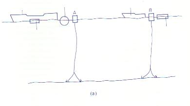
| Locating of the site for optimum depth, and anchoring of two mooring buoys; marking fast to one of the buoys a spherical float, the ship, and one of the four barges carrying the pipe segments; making fast the tug-boat and other three pipe-carrying barges to the second anchoring buoy (Fig.10a). | |
| The spherical float, suitably stabilized by counter-weights, is used as support during assembly. It is crowned by a hoist which will serve to introduce and lower the pipe segments through the circular well within the float. The first segment of the pipe is connected to the anchoring container (not yet ballasted )(Fig. 10b). | |
| Once the required pipe length is assembled, 200 T of iron ore will be introduced through the pipe itself, in order to ballbst the anchoring conainer and bring the spherical float below the surface (Fig. 10c). | |
| A hard-hat diver will then connect the central well of the ship to the assembled cold water intake pipe at the submerged float (Fig. 10c&d). |
3. The Ice Making Plant
Taking advantage of the cold (5¢J) water from the depths, and of favorable "other circumstance", G. Claude estimates that the temperature drop required to "manufacture frigories" needn't exceed 12 to 14¢J>, "instead of the 30 to 35¢J spread needed by ice plants supplied with water at 20 or 25¢J.. Thus the ocean will provide the energy while producing two and a half times more ice than the same energy sent ashore".
The 1300 KW Rateau rotray ammonia compressor is capable of producing 8000 negative calories per mechanical KWH, so the ice plant should be able to sustain a daily output of 2000 T of ice. The intention is to use only half of the operations. So,1000 m3 of fresh water will be required for the projected output of 1000 T of ice, and this fresh water will come from the condensation of the steam in the two surface action condenser compartments which have been designed to complement the mixing condensers.
The ammonia system operates at between 3.4 and 6 bars. The two freezers are contained within a flat bottom cylindrical enclosure of 5.5 meter diameter, with stoutly braced steel walls-40mm thick. The two bottom plates are connected by 12000 tubes, 1.4m long, their diameter tapering from 30 mm at the top to 24mm at the bottom end. They are force-fitted to the plates, and their lower ends are closed by wooden stoppers. It is within these tubes, immersed in an ammonia bath, that the water will freeze. A 2m high tank, located above the freezer tubes, will gravity-feed them with distilled water. This distilled water comes, as we have seen earlier, from the surface action condenses of the power-producing plant. The expected freezing times is 15 to 20mm. The addition of gaseous ammonia to the ammonia bath will, in a few minutes, raise its temperature enough for the freeing of the ice "candles", which will then float up to the top of the water tank. They will be collected mechanical waiting alongside the ship. It is expected that three completecylce can be accomplished per hour.
4. Operation At Sea:
A sea-bed depth survey taken with the Langevin-Florisson ultrasonic device pinpointed a 1 km area with fairly regular topography, in 600m of water, the depth varying by not more than 20m within the area. This area is 70m miles South of Rio Bay, and 130 km from the harbour (and not 100 km as had been hoped).
In January 1935, the placing of the first buoy is successful. The buoy is a metal cylinder, 1.5m in diameter and 3m high.
It is connected to a pair of 3t anchors by a 32mm steel cable, 800m long. After launching the cylindrical buoy, the 800m of cable are deployed floated by empty drums every 40m, along the surface; then the two anchors are attached and cast off. The body of the buoy, painted red, floats half-way out, and can be seen with the naked eye for 2.5 miles, and for 5 or 6 miles through binoculars.
The "La Tunisie" makes fast to the buoy, and spends several days testing the anchoring system in winds of 8 to 15 knots, with a surface current of 0.7 m/s. the strain on The cable will never exceed 5 tons.
Advantage is taken of the ship being on station for measurements of deep water temperatures, using two reversing thermometers lowered on a line, and kept at 8m above the bottom.
The accuracy of the measurements is of the order of 0.1¢J.Temperature fluctuations of the order of 1¢J are noticed at regular short intervals (about an hour). G. Claude is puzzled by this phenomenon that he cannot explain by the influence of the tides, and he puts forward the hypothesis of the possible existence of a "sort of deep-water swell action, of vast amplitude..."
The surface water that was at 24 to 25¢J in November is now at 27¢J as the assembly operation begins. We are, don't forget already in January , for the delays have been compounding. To start with, the "La Tunisie" didn't get to Rio before October 6, one month later than planned; then, a first load of pipe segments sank while being towed to the site.
Finally, after positioning the second anchor line, it was discovered that the two buoys were floating 200m apart, too short a distance for the mooring of the assembly flotilla, which includes, don't forget, seven different craft: La Tunisie, the spherical float, four barges and a tug. This mistake in the positioning of the anchors was simply due to a misconception at the time of placement. It had been assumed that the impact point of the two anchors would fall half-way between the respective positions of the ship and the buoy at the time of casting off. Actually, notes G. Claude, the final position turned out to be almost directly below that of the initial position of the buoy... So it becomes necessary to shift one of the buoys 1000m by retrieving the whole of the cable and anchors, over 8 tons of gear in 660m of water.
Thus it is four months behind schedule that, on February 8 1935, the assembly of the cold water intake pipe can finally begin. But the chances of seeing the plant operational before the end of the rapidly closing hot season are getting slimmer. The ocean swell is running high, and the Brazilian meteorological service lacks the necessary information to warm G. Claude of any impending bad weather out of the South and South-East. Bad weather which usually travels at 20 or 30 mph.
The spherical float, weighted by the hoist and stabilized by the first pipe segment of the cold water intake and its anchoring container is behaving "adequately", free of angular oscillations. The extent of the vertical surge often exceeds 2m.
The assembly of the first segments proceeds without problems. Assembly time goes from 50mn for the third, and it is completed in 36 hours. After placing the fourth segment, the spherical float begins to shake violentrly between the motions of the folat and of the anchoring container, which cannot follow the surface element.
G. Claude decides then to introduce a little ballast in the anchoring container, to weight it down. Unfortunately, as soon as the fifth segment is bolted into place, the fixing plates between the bottom of the pipe and the chains holding the anchoring container are wrenched off. It is now too late for repairs, and, furthermore, G. Claude can no longer afford the expense of the immobilized installation flotilla (over 150000 tons of commercial craft), or payroll and expenses for the 80 man workforce.
G. Claude decides to give up, after having personally "wounded to the death the superb apparatus (the float) with a shot of dynamite....", to deny himself any tempertation to renew the attempt.
Bibliography
| Communication from G. Claude to the Institute: "The La Tunisie Expedition" (not dated) | |
| Report of a visit by G. Claude to the Chantiers be France Shipyard in Dunkirk,29-07-34. | |
| "My life, my inventions"-G. Claude (autobiography) | |
| "Enter Nous", company magazine of the Chantiers de France, Dunkirk, No.62, December 1979 | |
| "current situation of my work on ocean thermal energy "G. Claude The Jourmal of "L' Academia Brasileira de Sciencias"-Vol. 6,31/12/34. | |
| French "Academic des Sciences" sessions, September 4 1933 and March 18 1935. |