Dossier Océan et énergie - Énergie Thermique des Mers
Sommaire IOA News Letters
THERMODYNAMIC ANALYSIS OF A 1 MW CLOSED CYCLED OTEC
PLANT OFF
THE INDIAN COAST
Prof. M. Ravindran C.
Balaji
Executive Director Visiting Scientist
National Institute of Ocean
Technology
Department of Ocean Development
IIT campus,
Madras
INDIA
ABSTRACT
Ocean Thermal Energy Conversion is one of the promising renewable energy options, particularly for countries close to the equator and having a long coastline, like India. Feasibility studies are currently underway at the National Institute of Ocean Technology, for the establishment of a 1 MW floating closed cycle OTEC plant. This paper reports the results of the thermodynamic cycle analysis carried out as a part of the feasibility studies for this plant. The analysis has been done for an ammonia based closed cycle OTEC plant. Environmental data (like temperature) used in the present study are based on previously measured experimental values. A parametric study has been done to study the effect of various variables like depth of cold water intake, on the performance of the plant.
INTRODUCTION
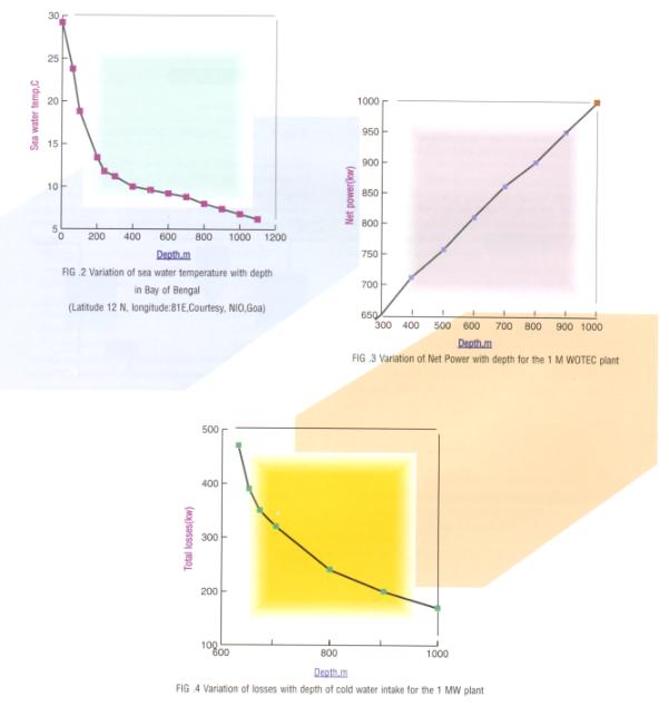
Between approximately 15o N and 15o S latitudes, the heat absorbed from the sun warms the surface sea water to a temperature near 28 ¢J. The fluctuation in the annual average temperature is only ±1 ¢J. Beneath this layer, water becomes colder with increasing depth, and at a depth of 1000 m, a temperature of about 4 ¢J is reached. Ocean thermal energy conversion (OTEC) process essentially uses this £G T to operate a heat engine, which produces electric power.
The concept of OTEC was first proposed by the French engineer Arsene d¡¦Arsonval in 1881. In 1930, George Claude designed and field tested an experimental system in Matanzas Bay, Cuba. This model generated 22 kW of power. However, the power consumed was more than the power generated. When the Gulf oil crisis of 1973 prompted an international search for alternate sources of energy, the potential for OTEC was re-examined. In 1979, a closed cycle Mini-OTEC plant in Hawaii produced net power for the first time, producing 18 kW (net). Heat exchangers for a 1 MW OTEC plant were successfully tested again in Hawaii in 1980. Since 1992, an open cycle OTEC plant generating 220 kW of power and producing potable water is operational at Keahole point, Hawaii. Research and development in OTEC technology has been witnessed sporadically in several other countries like France, Japan, Taiwan and Indonesia. The high cost of capital equipment required for OTEC, plagued by the absence of operational data from a full fledged pilot plant, have been the major deterrents hampering the commercialization of OTEC technology.
An excellent introduction to OTEC is provided by Takahashi and Trenka [1] and the current status of OTEC technology including finer details of various sub-systems has been dealt with extensively by Avery and Wu [2]. The current status of OTEC technology in the world and plans for the future are discussed in [3]. With major advances having taken place in heat exchanger technology as well as in offshore technology in the recent past, there is an increasing realization that OTEC may become commercially viable in the decades to come. This has led to a rejuvenated interest in OTEC in countries like USA and also in India. OTEC activity in India started off in the early eighties with the OTEC cell of IIT, Madras, preparing a preliminary report for a 1 MW plant off Andaman [5] and this was followed by other reports recommending different design options for sites in Lakshadweep and Andamans. However since 1987, there has been very limited activity on OTEC in India.
However, it needs to be emphasized that the potential for OTEC in India is very high. Ravindran and Kumar [3] in a recent study have estimated the OTEC potential in India to be about 180,000 MW. With such a high potential a critical look into the state of the art in OTEC technology with a view to establish a pilot plant would go a long way in giving India a wealth of experience as well as enormous operational data. This would be of much use in evaluating the commercial viability of establishing large size OTEC plants with a rating of 50-100 MW.
The above mentioned reasons coupled with the recent success of OTEC experiments in Hawaii have prompted India to take a fresh look again at OTEC technology. The Department of Ocean Development, Government of India has engaged its technical arm- The National Institute of Ocean Technology (NIOT), Madras to prepare a feasibility report for the establishment of a 1 MW OTEC plant off the Indian coast. This is expected to be followed by detailed engineering and later by the actual construction of the plant. The feasibility study currently underway at NIOT, involves conceptual design of the power conversion system, heat exchange equipment, sea water systems and structural design of the platform and the various pipes. This paper reports the results of the thermodynamic cycle analysis, which is crucial in establishing the sensitivity of the output of the power plant to various parameters besides being a major input to the actual design of all the equipment.
PROBLEM DEFINITION
Shown in figure 1 is a schematic sketch of a closed cycle OTEC plant. Warm sea water is used to vaporize ammonia and this drives a turbine. The exhaust of the turbine is condensed by the cold sea water and the liquid ammonia is pumped back to the evaporator. The operating pressures of this organic Rankine cycle are in the range of 6-9 bar and the poerating temperature range is 6-29 ¢J. Ammonia is preferred because of its superior transport properties and also because of its easy availability and low cost [2]. The problem under question actually involves the following:
- For a particular location of the Indian coast, temperature versus depth profile in the sea has to be obtained.
- The operating pressures and temperatures of the ammonia cycle have to be fixed, considering appropriate temperature differences between ammonia and water across the heat exchangers.
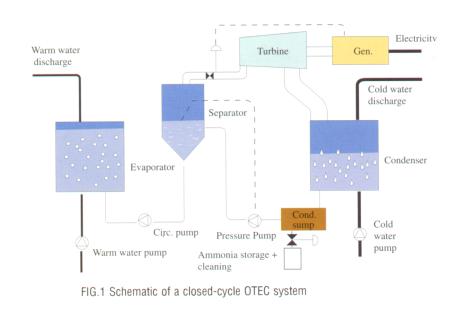
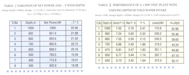
- The flow rate of ammonia and the sea water (both warm water and cold water) have to be established by energy balance, taking into account the isentropic turbine efficiency, as well as mechanical and electrical losses involved in converting the thermal energy of sea water into electric power. A major component of the losses is the frictional loss involved in bringing up cold water to the surface through the cold water pipe ( CWP ).
- Step (c) is necessarily iterative because, the measure of total losses in the system i.e., sum of pumping losses, mechanical and other losses, is a prerequisite for obtaining flow rates of ammonia and sea water. However, these losses are themselves functions of these flow rates. So, an iterative scheme has to be employed so that convergent values of ammonia and sea water flow rates are obtained.
ANALYSIS
- ASSUMPTIONS
-
Efficiencies of all pumps considered in the analysis is 85%.
- Isentropic turbine efficiency is 75%.
- ¡µ T across the heat exchanger for both warm and cold sea water is 4 ¢J. Terminal Temperature difference in both evaporator and condenser is 1 ¢J .
- Diameter of the cold water pipe is 1.2 m and it is made of concrete [5].
- The OTEC plant is located off shore and hence length of the cold water pipe is equal to the depth of cold water intake.
- Heat exchanger design is available and pressure drop versus velocity data is available. In this study the shell and tube heat exchangers proposed in [5] are considered. However, the analysis is broadly applicable for a plant with plate heat exchangers also since in both the cases the frictional head losses are proportional to the square of fluid velocities, and so the qualitative variation of performance parameters will be similar for plants with shell and tube or plate heat exchangers.
-
- METHODOLOGY
First, a particular location in the east coast of India was chosen (12o N and 81o E) and for this the environmental data (i.e. temperature vs depth) is available [4]. It needs to be mentioned that as long as the location is sufficiently far off from the coast, the temperature vs depth profile for any other location will be very much similar to this and the results of this analysis should, hence, the theoretical maximum efficiency to be 1- ¡ü£¾ Tc/TH. It can be seen that the actual efficiency varies from 67% of the maximum efficiency at 1000 m depth to 48% of the maximum efficiency at a depth of 630 m.
CONCLUSIONS
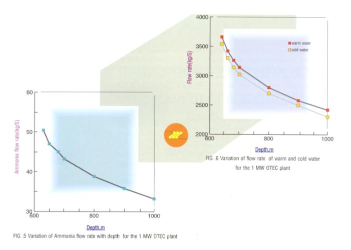
A thermodynamic analysis of a 1 MW closed cycle (ammonia based) OTEC plant was carried out. Measured values of sea water temperatures as a function of depth was used for the analysis. A realistic estimation of the pertinent losses in the system was done and the design parameters for a power of 1 MW for a depth of 1000 m were established. The sensitivity of these parameters to changing depth of cold water intake was studied in detail. Net power was found to vary quadratically (exponent of 2.04) with depth.
REFERENCES
- P. Takahashi, A. Trenka, Ocean Thermal Energy Conversion, 1996, John Wiley and Sons, England.
- W. H. Avery, C. Wu, Renewable Energy from the Ocean, 1994, Oxford University press, New York, USA.
- D. Tanner, OTEC-A clean energy whose time has come, 1996, Emerging Technology Series, Marine Industrial Technology, United Nations Industrial Development Organization, Vienna, p 1.
- M. Ravindran, B. Nagendra Kumar, Assessment of OTEC potential and promises for India, 1996, presented at the International workshop on Renewable Energy Technologies, Anna University, Madras, India.
- Preliminary Design for the proposed 1 MWe OTEC plant off the Indian Coast, 1981, OTEC project cell, IIT Madras, India.
- W. E. Stoecker and J. W. Jones, Refrigeration and Air Conditioning, 1982, Mc Graw Book Company, Singapore.
- C. Wu, A performance bound for real OTEC engines, 1987, Ocean Engineering, p.349.
Nomenclature
| £Gp pressure drop, bar | |
| £GT temperature difference, ¢J | |
|
m flow rate, kg/s | |
| P power, kW | |
|
T temperature, ¢J | |
|
TH temperature of warm sea water, K | |
|
TC temperature of cold sea water, K |
Greed
£befficiency, output power/heat supplied
Subscripts
CSW
cold-sea water
NH3
ammonia
WSW
warm sea water