Dossier Océan et énergie - Énergie Thermique des Mers
Sommaire IOA News Letters
UTILIZATION OF DEEP OCEAN WATER FOR SEAWATER DESALINATION
by
John P.
Craven, Ph.D.
President, Common Heritage Corp., Honolulu, Hawaii,
U.S.A.
and
Patrick K. Sullivan, Ph.D., P.E.
President, Oceanit
Laboratories, Inc., Honolulu, Hawaii, U.S.A.
INTRODUCTION
The utilization of deep ocean water for the generation of electricity, aquaculture, cold water agriculture, air conditioning, industrial cooling, and desalination has been investigated by a number of clients at the Natural Energy Laboratory of Hawaii Authority (NELHA)1. In 1988, Oceanit Laboratories, Inc. (Oceanit) described the use of deep ocean water as a resource in its study for the U.S. Trade Development Program (USTDP),Department of Commerce.2 Common Heritage Corporation
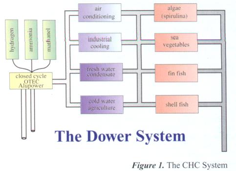 (CHC) has defined parameters for a small, self-sufficient,
environmentally sustainable system for use by small coastal villages having
access to deep ocean
water.3 The
system (Figure1) utilizes the deep ocean water sequentially for three
temperature regimes in three subsystems: the Electrical Power Generating System
(4-8 ¢J),the Cold Utilization System(7-10 ¢J), and the
Nutrient Utilization System (>10 ¢J).
(CHC) has defined parameters for a small, self-sufficient,
environmentally sustainable system for use by small coastal villages having
access to deep ocean
water.3 The
system (Figure1) utilizes the deep ocean water sequentially for three
temperature regimes in three subsystems: the Electrical Power Generating System
(4-8 ¢J),the Cold Utilization System(7-10 ¢J), and the
Nutrient Utilization System (>10 ¢J).
The Electric Power Generating System takes advantage of the difference in temperature between surface water and the deep ocean water, referred to as Ocean Thermal Energy Conversion (OTEC). This difference is small and geographically limited because large flows are required to produce small amounts of power. The Cold Utilization System takes advantage of the extremely low cost of cold seawater (<10 cents per 1,000 gallons) for the purpose of cold water agriculture, and/or air conditioning and industrial cooling, and/or desalination. The low cost of the deep ocean water is such that the economic advantages of utilizing this fluid for these applications are overwhelming. The Nutrient Utilization System takes advantage of the deep ocean water purity and its nutrient content. This gives an economic and public health advantage vis-a-vis aquaculture systems that must use the nutrient poor, highly polluted, diseased surface waters.
CHC developed or evaluated low cost techniques for the full utilization of the deep ocean water. Except for electricity generation, all components are sufficiently developed for economic utilization in small coastal systems. The lowest cost production of fresh water is through the simple utilization of the condensate that forms on inexpensive heat exchangers. The application of used automobile radiators4 has proven effective. CHC has empirically demonstrated that approximately 5% of the quantity of ¡§pass through ¡§ deep ocean water can be generated in the form of fresh water condensate. For a typical radiator, this is the equivalent of approximately 4 inches f rain day (1,200 inches per year) based on the frontal area of the radiator. If the radiator is elevated, then the water generated can be collected in a reservoir that feeds the system by gravity. The use of a siphon for the elevation of the cold water allows the generation of this fresh water too occur at approximately 30 feet above sea level.
The success of this elemental desalination system led to the question as to whether the condensation process can be significantly enhanced by an increase in the quantity and flow rate of surface seawater vapor that can be exposed to the deep ocean cold environment. Recognizing that nature very often generates the most efficient processes for producing natural energy products5 (i.e., the production of orographic rain in trade wind regions by topographic configurations), it was decided to examine the hurricane to determine the manner in which it generates rain and to simulate this phenomenon in a micro-climate structure that we now call a ¡§ Hurricane Tower.¡¨ The first results of this simulation are presented here.
THEORY AND DESIGN
During the summertime, patches of surface water in the tropics are exposed to intense solar radiation. As these patches of water randomly migrates in a Northerly or Southerly direction, the earth ¡¦ s rotation creates patches of warm water vortices that rotate clockwise in the Northern Hemisphere and counter clockwise in the Southern Hemisphere. This is known as the Coriolis effect. Air-sea interaction produced vorticity in the atmosphere that also behaves as a fluid , albeit a compressible fluid. These vortices tend to coalesce into a single large vortex of increasing energy density (¡§ Big whorls feed on little whorls and so on to vorticity¡K¡¨ ). Initially, the coalesced vortex mass appears as a tropical storm. If the solar activity is intense and the surface waters are warm, the vortex will roll up into a tight column that approximates an ideal irrotational vortex. This vortex is called the core of a hurricane. If the hurricane passes over cool water or over land, energy is no longer fed into the hurricane and viscous dissipation takes over(¡§¡K .little whorls feed on big whorls and so on to vorticity .¡¨ ). The hurricane then reverts to a tropical storm and ultimately blends with the normal atmosphere.
The high velocity at the core of the hurricane produces low pressure due to the Bernoulli effect. At the air-sea interface, the relative velocity between air and water is virtually zero and the wind velocity within this boundary layer is greatly reduced. This results in a vertical pressure gradient that carries the surface moisture upward along the face of the hurricane core. This upward flow of air becomes part of a secondary vortex that spirals upward around he core of the hurricane until it hits the boundary of a cloud of ice called the lenticular could. This cloud results from the cold temperature of the high altitude and the expansion of the moist updraft. The ice cloud now produces condensate in the form of rain that returns to the surface of the sea. This secondary vortex, in turn induces a tertiary vortex and so on. Thus there are bands of updraft and bands of rain swirling around the central core.
The secondary vortex phenomenon can be observed in containers of fluid having rigid boundaries such as cups and pails and is often referred to as the teacup or coffee cup phenomenon6 . The presence of this secondary vertical vortex is easily demonstrated by stirring a cup of tea and watching the movement of the tea leaves in the cup. In this simple experiment, a central vortex is generated through the stirring of the tea. This central vortex appears regardless of the manner in which turbulence is introduced in the stirring of the tea. At the boundaries of the cup, stagnation zones are created that produce pressure gradients, which generate the flow of the secondary vortex. At the surface, the tea leaves will disperse to the outside of the cup. They are then vectored to the bottom and to the center of the cup. Eventually, they rise, in rotation about the central vortex becoming dispersed again throughout the cup at the surface and then back to the bottom.
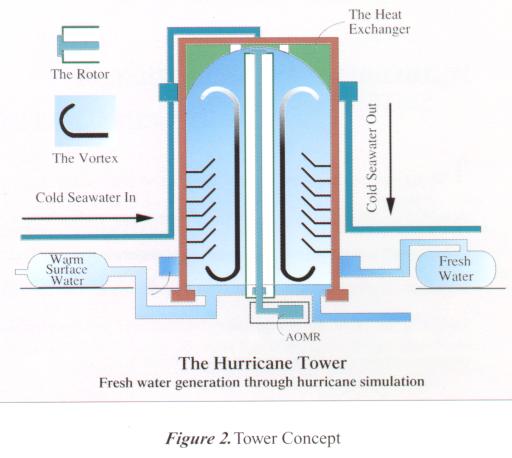
Having demonstrated the equivalence of the hydrodynamic phenomenon in both a hurricane and a teacup, the designer is now in a position to develop a micro-hurricane within the confines of a tower. The concept design is shown in Figure 2. Warm surface water is passed through the bottom of the tower and water vapor thus generated is lifted by the secondary vortex at the top of the tower where it meets a heat exchanger that simulates the lenticular could. The heat exchanger is kept cold by deep ocean water that circulates through the exchanger at the top of the tower. The resulting ¡§ rain¡¨ is captured in trays at the top of the tower and sorted in an elevated water tower for distribution by gravity to the consumer.
The energy efficiency of this tower derives from the fact which is the energy of the vortex (normally a wasted energy) that is the lifting energy of the water vapor. If , for example, the rotor was to rotate in a vacuum, the energy required for rotation would be insignificant. Thus, as with a propeller, an airplane wing or a Flettner Rotor, the energy required to produce the vortex is the energy required to produce the flow pattern that results in the lift of the vapor to the cooling coils at the top of the tower.
Conceptually, a Hurricane Tower could provide a protable and efficient water desalination device that utilizes abundant natural resources of deep cold ocean water, warm tropical surface waters, and solar energy to provide most of the power for the system. The concept of utilizing the dynamics of generated secondary vortices to move the saturated air up the column to the cold condensation plate is both unique and energy efficient (patent pending). Several of these devices could be placed on a barge to create an inexpensive mobile vortex-principle water desalination plant for military troops, island states (e. g ., Hawaii ), territories, atolls, Third World nations and coastal drought areas to increase fresh water supply routinely, on demand, and during emergencies.
EQUIPMENT AND PROCESSES
A scaled prototype was designed and constructed by Oceanit at CHC ¡¦s facility at NELHA located at the Keahole Point, Kona, Hawaii to investigate the fesibility of this concept as well as to identify the important design parameters for a full-scale production version. Warm surface seawater used as the evaporative fluid and cold deep ocean water used for the condenser coils at the top of the tower were supplied by CHC; the study was funded by the National Science Foundation (NSF) and the High Technology Development Corporation of Hawaii (HTDC) under SBIR grants to Oceanit. The project is a joint venture between Oceanit and CHC. CHC is not supported by any government agency or non-profit foundation.
The primary purpose of the experiment was the demonstration that the configuration would operate as designed and generate fresh water in accordance with theory. The tower was not optimized to maximize fresh water production any more than Mini-OTEC was optimized for the production of net power or the Wright Brothers airplane was optimized for the prolongation of flight. An exploration of the secondary vortex formation was performed to quantify its behavior relative to the tower configuration and rotor velocity. Further experiments were performed to quantify relations between various parameters and water production. These experiments verified the validity of the concept and provide information for design and development of full-scale systems.
The Hurricane Tower pre-prototype model was constructed at NELHA, located at Keahole Point, Kona, Hawaii. The Tower was constructed with a 20-foot long section of 8-foot (inside diameter) fiberglass pipe with a wall thickness of 2 inches. The section of pipe was placed upright, anchored to a concrete pad and caulked at the bottom to provide a water tight seal for the evaporative pool, provided with inflow and drain pipes through the cement pad. Inflow warm seawater to the tower was provided through the surface seawater of CHC. This water is typically about 82¢K and 35 parts per million (ppm) salinity from the ocean source. It was further warmed in a 16-foot diameter, 1.5-foot deep solar pond covered with a sheet of clear plastic. Depending on water flow through rates and sun height, this solar pond increased the incoming water temperature to the base of the tower evaporative pool 2- 10¢K to a maximum of 92 ¢K.
The tower was capped at the top with plywood deck that serves as the base for the motor and top rotor bearing. A light roof structure was added to project the equipment from the weather. The plywood deck was fastened securely to the pipe tower to minimize vibrations and to seal the atmosphere within the Hurricane Tower.
The motor and top bearing assembly were affixed to a 0.5 ¡Vinch steel plate bolted to the plywood base. The thrust bearing for the base of the rotor was bolted to a raised concrete foundation in the middle of the evaporative pool. Total distance from the bottom of the plywood deck to the base of the pool below was 19 feet 4 inches.
The heat exchanger system was installed using approximately 175 feet of tubing (total surface area 28.6 square feet) and was arranged in a spiral fashion supported by fiberglass structural members creating a dome. Cold seawater (46.7 ¢K) from the NELHA plumbing system was fed to the exchanger at a height of 18.2 feet and exited the coils at a height of 16.5 feet. Thermistors were inserted in the cold water line at its point of entry and exit from the chamber.
Six access ports were installed at 3-foot intervals up the wall of the tower beginning at 1 foot above the concrete pad. These ports were used primarily for velocity surveys of the flow field by inserting a pivot tube through each port and taking wind speed measurements from the outer wall edge to the surface of the spinning interior rotor. Two 8-inch diameter observation windows covered with 0.25-inch plexi-glass were installed at heights of 5.5 feet and 16.5 feet to aid in flow visualization and visual monitoring of the inner chamber. A 21-inch diameter access hole was placed near the bottom of the tower to allow entrance into the chamber for construction and rotor modifications. This access hole was closed and sealed during normal testing.
A solar heating tank
was constructed from a standard commercially available 16-foot diameter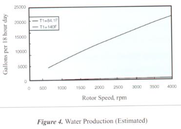 , plastic lined, above ground swimming pool. A sheet of
clear plastic was fastened over the top of the pool to help trap the solar heat
within the pool. Warm water exited the pool via a surface skim drain at the
center of the pool. Temperature of the solar heated water was measured as it
entered the base of the Hurricane Tower. Saltwater flow rate into the tower was
controlled by metering the inflow into the solar heating pool.
, plastic lined, above ground swimming pool. A sheet of
clear plastic was fastened over the top of the pool to help trap the solar heat
within the pool. Warm water exited the pool via a surface skim drain at the
center of the pool. Temperature of the solar heated water was measured as it
entered the base of the Hurricane Tower. Saltwater flow rate into the tower was
controlled by metering the inflow into the solar heating pool.
THEOREITCAL CALCULATIONS OF SYSTEM PERFORMANCE
The basic mechanism around which the Hurricane Tower is designed is the rotor, which produces a primary vortex where the axis is parallel with the rotor axis and a secondary vortex that acts as a continuous circular filament surrounding the rotor. The secondary vortex is induced by the primary vortex and the no-ship fluid condition at the tower floor and at the walls of the tower.
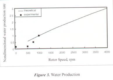
The effect of rotor speed on water production was experimentally investigated even with non-ideal cooling coil configuration. Water production was greatly enhanced by rotor speed. Theoretical water production for the Hurricane Tower as a function of rotor speed for warm water temperature of 81.4 ¢Kand cold water temperature of 41.6¢K is shown in Figure 2. Theoretical production increases approximately one order of magnitude by solar heating water to approximately 140¢K , as shown in Figure 3.
DESALINATED WATER QUALITY
Water produced by the Hurricane Tower was tested for total dissolved solids (TDS) and Chlorides. The results are shown in Table 1 along with drinking water results and typical Kona seawater quality in parts per million (ppm).
Table 1
Water Quality Results
for Hurricane-Tower-Desalinated Water
as Compared to Seawater and Local Tap
Water Quality
|
Water Source |
TDA (ppm) | Chlorides (ppm) |
| Seawater | 35,000 | 19,000 |
| Kona Tap Water | 712 | 265 |
| Hurricane Tower Water | 10 | -5 |
RESULTS
The experiments clearly demonstrated the validity of the Hurricane Tower design principles. The aerodynamic flows in the tower were as predicted and result from the effective operation of a practical and inexpensive rotor. The production of water was a function of the velocity of the indicating the effectiveness of the secondary vortex in lifting the water vapor to the cooling tower. On the basis of a heuristic model as applied to the test configuration and the actual results, it may be concluded that a tower of the size of the prototype can produce from 25,000 to 50,000 gallons of water per day provided that the intake water in pre-heated in a solar salt pond or by direct solar heating. Since the production should be roughly proportional to the square of the diameter of the tower, continued development of the concept is clearly warranted.
REFERENCES
1.Daniel, T.H. ¡§ Deep Ocean Water Utilization at the Natural Energy Laboratory of Hawaii Authority,¡¨ paper presented at the Oceanology International ¡¥ 94 Conference, Brighton, United Kingdom, March 8-11, 1994.
2.Sullivan, Patrick K, Oceanit Laboratories, Inc. ¡§ Deep Ocean Resource Recovery and Utilization System (DORRUS)¡¨ prepared for the U.S. Trade and Development Program, International Cooperative Agency, Department of Commerce, 1998.
3.Craven, John P. ¡§ Realistic Self Sufficient Coastal Zone Complexes Using Deep Ocean Water as a Resource,¡¨ paper presented at the Coastal Ocean Space Utilization (COSU) Conference ¡¦ 95, Yokohama, Japan, 1995.
4.Fast, Arlo. ¡§ Air Conditioning of a Research Facility Through the Use of Deep Ocean Water Flowing Through an Automobile Radiator and a Fan, ¡¨ an empirical demonstration at the Natural Energy Laboratory Hawaii Authority (NELHA), crica 1983.
5.Gersid and Worzel. ¡§ Condensation of Atmospheric Moisture From Tropical Maritime Air Masses as a Freshwater Resource,¡¨ Science, 157, pp 1300-1302, 1967.
6.Baker, D .J. ¡§ Demonstrations of Fluid Flow in a Rotating System II: The ¡¥ Spin-Up¡¦ Problem,¡¨ American Journal of Physics 36 (11),pp. 980-986, 1968.